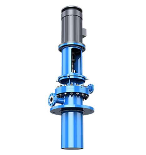
Standard Design Of The double casing Canned Vertical barrel centrifugal Turbine Pump
The suction and discharge lines shall be completely filled with liquid prior to start up. The suction line can be for instance sloped up towards the tank to ensure that no gas pocket is present in the suction line.
The suction CAN itself must also be vented as shown in the Figure 4. Vent line shall be always kept open to allow venting of gas at all times.
Furthermore, the API Plan 13 must be designed with a venting line to ensure that no gas will be trapped in the column pipes (discharge side of the double casing Canned Vertical barrel centrifugal Turbine Pump).
To ensure positive venting, all vent lines must be connected to the gas phase of the suction tank.
Shall the vent line of the CAN (N3) be led to the flare instead of the suction tank, a restricted orifice
shall be installed in this line in order to reduce the volumetric losses.
Gas Coffer Dam Design
To prevent icing of the mechanical seal, all Canned Vertical Turbine Pumps (double casing vertical barrel centrifugal pumps) handling liquids at temperatures below -50°C (60°F) are fitted with a gas coffer dam.
The gas coffer dam (discharge side) is vented via the balancing line (N5 of Fig.5). The balancing line shall be connected to the gas phase of the suction tank.
The line shall be kept open during operation.


